
Views: 0 Author: Site Editor Publish Time: 2026-07-15 Origin: Site


Running degraded tooling silently drains shop efficiency. Spindle wear accelerates, material spoilage rates climb, and edge finishes suffer in precision manufacturing. Operators often struggle to determine if a tool is genuinely dull or simply fouled with baked-on pitch. Altering factory tool geometry through improper maintenance introduces severe operational risks, leading to unpredictable cutting behavior and scrapped parts. Establishing a strict tooling maintenance protocol solves these daily production issues. You must implement a standardized cleaning process before attempting any abrasive material removal. Evaluating in-house touch-up capabilities against the precision of professional regrinding determines your overall tooling efficiency. Understanding the exact geometry of your cutting tools allows you to make informed decisions about when to sharpen and when to replace. We will outline the exact steps to diagnose wear, clean effectively, and maintain precise cutting tolerances.
Diagnosis Before Action: Over 50% of perceived dullness is caused by resin and pitch buildup; chemical cleaning must precede any abrasive sharpening.
Geometry is Non-Negotiable: Proper sharpening requires removing material exclusively from the inside flute (face) to maintain the outside diameter (OD) and cutting profile.
The ROI Threshold: High-performance tooling, such as solid carbide spirals, typically warrants professional CNC regrinding, while cheaper brazed bits often favor direct replacement.
Post-Sharpening Calibration: Resharpened bits have a reduced cutting diameter, requiring mandatory adjustments to CAM software toolpaths and feed/speed rates to prevent chatter.
Optimal cutting performance relies on maintaining a precise chip load. A sharp tool shears material cleanly, pulling heat away from the cutting edge through the ejected chips. When Router Bits lose their edge, they begin to rub and compress the material rather than cutting it. This friction generates extreme heat, degrading the carbide binder and causing burn marks on the workpiece. Maintaining optimal chip load efficiency requires a pristine cutting edge. You can hear a dull tool before you see the results. The machine will emit a higher-pitched whine, and the spindle load meter will show a noticeable spike during standard profiling operations.
Operators must establish a baseline for optimal cutting performance. This baseline includes monitoring the physical appearance of the chips, the sound of the cut, and the surface finish of the final part. When chips turn into fine dust, the tool is no longer shearing effectively. When the edge finish shows tear-out or fuzz, the cutting geometry has degraded. Documenting these baseline metrics allows operators to pull tools before they fail catastrophically.
Detecting tool wear early prevents catastrophic failure and protects your spindle. Visual and tactile inspections provide immediate feedback on tool condition. You should perform these checks at the end of every major production run.
The Fingernail Test Mechanics: Hold the cutting edge against your fingernail. Gently rotate the tool. A sharp edge will cleanly shave the nail with minimal effort. A dull edge will slide or scratch the surface without biting into the nail. This tactile feedback is the fastest way to assess edge degradation on the shop floor.
Visual Inspection Techniques: Inspect the cutting edges under a 10x to 20x magnification loupe. Look for micro-fractures along the flute. Identify any heat discoloration, which indicates the tool has been rubbing. Check for rolled edges where the carbide has physically deformed under stress. Pay close attention to the tip of plunge-cutting tools, as this area experiences the highest thermal shock.
Surface Finish Degradation: Monitor the edge quality of your cut parts. A sharp tool leaves a mirror-like finish on plastics and a clean, fuzz-free edge on hardwoods. If you start seeing chatter marks, burning, or excessive tear-out, the tool geometry is compromised.
Dull tooling exponentially increases the lateral load on the machine spindle. As the tool struggles to shear the material, the machine must push harder to maintain the programmed feed rate. This excessive force transfers directly to the spindle bearings. Premature bearing failure causes structural runout, introducing vibration into every subsequent cut. Energy consumption spikes as the spindle motor draws more current to overcome the increased cutting resistance.
The mechanical strain extends beyond the spindle. The gantry drive motors and ball screws experience increased resistance, leading to accelerated wear on the entire motion control system. Vacuum hold-down systems struggle to keep parts stationary when dull tools exert excessive lateral force. Parts may shift during the cut, ruining the workpiece and potentially causing a collision. Replacing a ruined spindle or repairing a damaged ball screw requires significant downtime and capital expenditure. Maintaining a proper tooling rotation prevents this systemic machine strain.
Wear Indicator | Physical Symptom | Impact on Production |
|---|---|---|
Micro-fractures | Visible chips missing from the carbide edge under magnification | Leaves raised lines on the cut edge, accelerates further tool degradation |
Rolled Edge | Carbide edge physically bent backward, losing its sharp point | Causes severe rubbing, extreme heat generation, and material burning |
Heat Discoloration | Blue or black tint on the carbide or tool steel body | Indicates loss of temper in brazed joints, high risk of catastrophic failure |
Pitch Buildup | Sticky, dark residue packed into the flutes and behind the cutting edge | Restricts chip evacuation, mimics dullness, increases spindle load |
Chemical restoration must always precede mechanical restoration. Attempting to sharpen a dirty tool embeds resins into your diamond honing stones and alters the grinding angle. Pitch buildup simulates a dull edge by restricting chip flow and altering the clearance angle. You must isolate the root cause of poor cutting performance before removing any carbide material.
Many shops throw away perfectly good tooling simply because it is dirty. A thick layer of baked-on resin changes the physical dimensions of the tool. It fills the flute valley, preventing chips from curling and ejecting properly. The tool recuts these trapped chips, generating massive amounts of friction. This friction heats the carbide, softening the binder and accelerating actual edge wear. Cleaning the tool restores the original flute volume and allows the tool to function as designed.
Wood resins, sap, and synthetic adhesives bond rapidly to carbide under high heat. This baked-on pitch accumulates behind the cutting edge. As the layer thickens, it reduces the clearance angle between the tool and the workpiece. The tool begins to ride on the pitch rather than cutting with the carbide edge. This restricts chip clearance, causing chips to recut and generate more heat. The resulting friction mimics the exact symptoms of a dull tool.
Machining composite materials like MDF or melamine accelerates this process. The glues and binders in these materials melt at high temperatures and stick to the tool surface. Once a thin layer of pitch forms, it acts as an insulator, preventing the tool from shedding heat. This thermal trap causes the pitch layer to grow exponentially faster. Regular cleaning intervals prevent this runaway thermal degradation.
Aggressive mechanical cleaning damages polished carbide surfaces. You must rely on chemical solvents to break down the pitch. Follow these exact steps to restore your tooling without damaging the cutting geometry.
Chemical Soaking: Submerge the cutting flutes in an industry-standard solvent. A 50-minute soak in a citrus-based or alkaline-based cleaning bath effectively releases baked-on pitch. Keep the tool shank out of the solvent if possible to protect laser-etched identification marks. Use a dedicated soaking tray with a suspended rack to prevent the carbide edges from banging against each other.
Debris Removal: Never use wire brushes or abrasive steel pads. These materials create micro-scratches on the polished carbide flutes. Scratched flutes disrupt chip evacuation and encourage faster pitch buildup in the future. Use a nylon bristle brush or a brass brush to gently scrub away the softened resin. Work the brush parallel to the flute to avoid rounding over the cutting edge.
Rinsing and Moisture Displacement: Thoroughly rinse the tool with clean water immediately after removing it from the solvent. Dry the tool completely using compressed air. Ensure no moisture remains in the flute valleys or around the brazed joints.
Rust Prevention: Apply a light coat of moisture-displacing oil or dry lubricant to protect tool steel shanks and brazed joints from flash rusting. Wipe off any excess oil before returning the tool to inventory, as wet oil will attract dust and debris.
Maintaining precision requires choosing the correct sharpening method based on tool geometry and wear severity. Manual honing extends the time between professional regrinds, but it cannot restore complex factory angles. You must evaluate the specific needs of your production environment to determine the best approach.
In-house maintenance focuses on edge restoration, while professional services focus on geometric reconstruction. Understanding the limitations of manual honing prevents operators from accidentally ruining expensive tooling. We will break down the specific techniques required for both approaches.
Manual honing requires a steady hand and strict adherence to geometric principles. You can restore a micro-edge using diamond abrasives. This process is only suitable for straight-fluted tools or simple profiles with minor wear.
Diamond Paddle Selection: Use high-quality diamond paddles for carbide tooling. Start with a 600-grit paddle to remove minor nicks. Finish with a 1200-grit paddle to polish the cutting edge. Lubricate the paddle with lapping fluid or water to float away carbide swarf. Dry honing clogs the diamond abrasive and generates unnecessary heat.
Maintaining Face Angles: You must strictly hone only the flat face of the inside flute. Never touch the beveled outside relief angle. Removing material from the outside diameter instantly alters the tool's clearance angle and ruins its cutting profile. Keep the diamond paddle perfectly flat against the flute face during every stroke. Count your strokes to ensure even material removal across all flutes. Uneven honing induces tool runout and vibration.
Burr Removal: After honing the inside face, you may feel a microscopic burr on the outside edge. Do not grind the outside edge to remove it. Instead, make one very light, trailing pass with a piece of hardwood against the cutting edge to shear off the burr cleanly.
Industrial sharpening restores the exact factory specifications of your CNC Router Bits. Professional services utilize advanced machinery to handle complex geometries. This is the only acceptable method for maintaining high-performance production tooling.
Multi-Axis CNC Grinding: Professional services use multi-axis CNC tool grinders. These machines map the existing tool geometry using laser probes. They precisely remove material to restore the exact factory rake and clearance angles. This process guarantees concentricity and balance. The machines flood the grinding zone with coolant to prevent thermal damage to the carbide binder.
Tip Geometry and Point Splitting: Plunge-cutting tools require specialized tip geometry. Professional grinders re-establish split points, fish-tail ends, and complex ball-nose profiles. Manual honing cannot accurately recreate these critical plunge-cutting features. A poorly sharpened tip will cause the tool to wander during plunge operations, ruining the part and potentially snapping the bit.
Surface Coating Restoration: Many high-performance tools feature specialized coatings like Titanium Aluminum Nitride (TiAlN). Professional services can strip the remaining degraded coating and re-apply a fresh layer after grinding, restoring the tool's original heat resistance and lubricity.
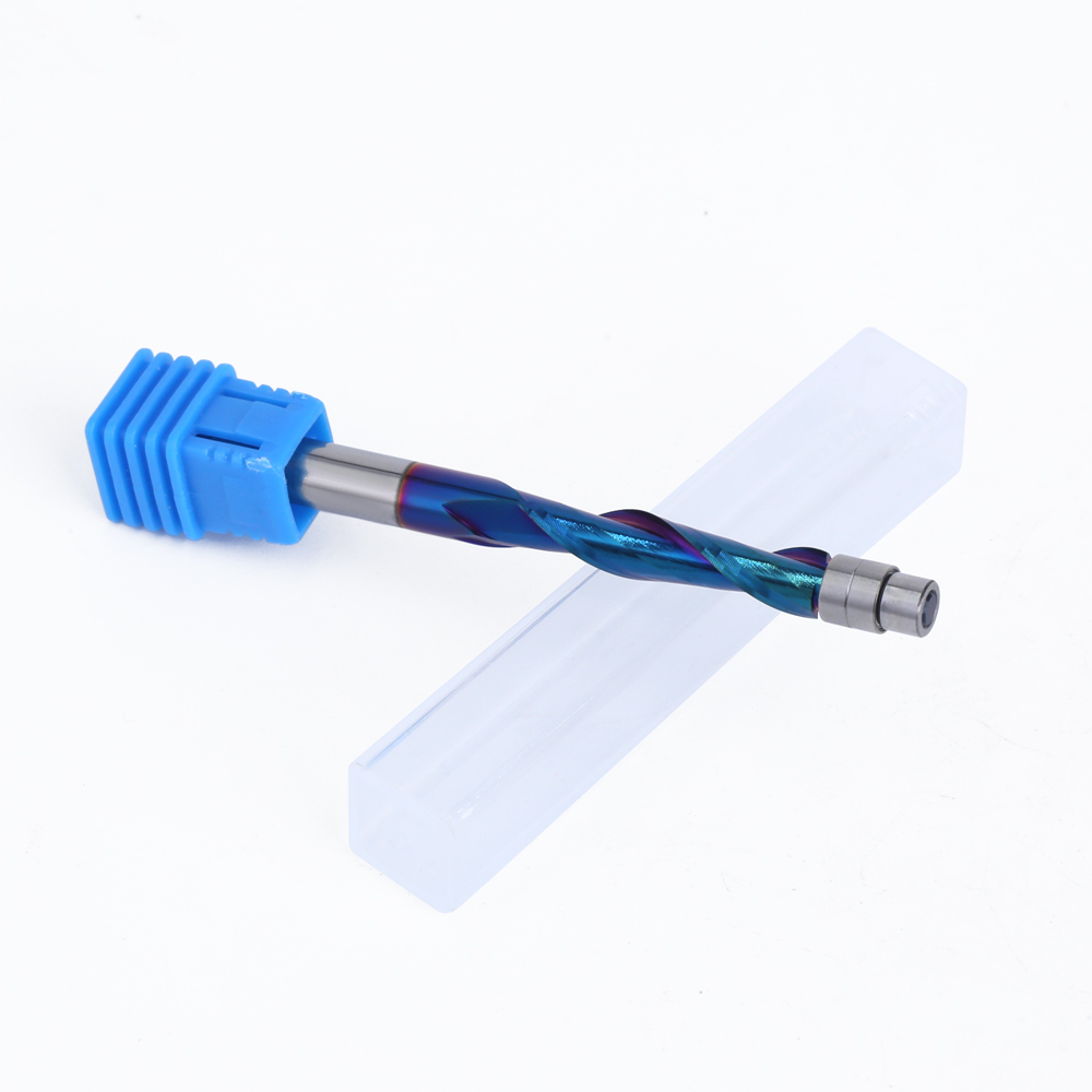
Flush trim bits present unique geometric challenges during the sharpening process. The cutting edge must align perfectly with the guide bearing. Any deviation results in a flawed cut.
The Alignment Dilemma: Sharpening removes material, slightly reducing the cutting diameter. If you sharpen Solid Carbide Flush Trim Bits, the cutting edge diameter no longer matches the standard guide bearing. This misalignment causes the tool to leave a slight step or gouge the template during flush-cutting operations. The tool becomes useless for precision template routing.
Post-Sharpening Adjustments: You must replace the original guide bearing after sharpening. Install a matched, undersized bearing that corresponds exactly to the new, reduced cutting diameter. This restores exact flush-cutting accuracy and prevents template damage. You must measure the new cutting diameter with a micrometer to select the correct replacement bearing.
Altering tool geometry through improper sharpening leads to catastrophic failure. Asymmetrical sharpening causes tool runout, where one flute does all the cutting. This induces severe vibration, destroys surface finish, and shatters the carbide. You must understand the physics of the cutting edge to maintain accuracy.
The relationship between the rake angle, the clearance angle, and the cutting edge radius dictates how the tool interacts with the material. Changing any of these variables alters the chip formation process. We will examine the critical geometric factors that must be preserved during maintenance.
The fundamental rule of sharpening is to grind the inside flute face first. Altering the outside diameter (OD) ruins the bit's clearance angle. If you grind the OD, the heel of the tool will rub against the material before the cutting edge engages, causing severe burning. Professional grinders will only perform a light touch-up on the OD relief angle when the clearance angle becomes critically small after multiple face grindings.
Grinding the inside face maintains the original cutting profile. For complex molding bits, this is the only way to ensure the routed profile matches the original design. Removing material from the face slightly reduces the overall diameter, but it preserves the exact shape of the cut. You must accept this diameter reduction and compensate for it in your software.
High-RPM spindles demand perfectly balanced tooling. Removing material unevenly during sharpening shifts the tool's center of mass. Even a fraction of a gram of imbalance creates destructive centrifugal forces at 18,000 RPM. Professional sharpening services dynamically balance the tools after material removal. This ensures smooth operation, protects spindle bearings, and eliminates chatter marks on the workpiece.
Unbalanced tools create a harmonic resonance that travels through the machine frame. This resonance causes the cutting edge to bounce against the material, leaving a rippled surface finish. Over time, this vibration destroys the precision bearings in the spindle cartridge. You cannot balance a tool manually; it requires specialized dynamic balancing equipment.
A resharpened tool is physically smaller than a new tool. You must adjust your machining parameters to compensate for this reduced diameter. Operating a resharpened tool with the original factory parameters will result in poor performance.
Measure the New Diameter: Use a calibrated micrometer to measure the exact cutting diameter of the resharpened tool. Do not rely on calipers, as they are not accurate enough for this measurement.
Calculate the New Surface Speed: A smaller diameter tool travels less distance per revolution. To maintain the same surface speed (SFM), you must slightly increase the spindle RPM.
Adjust the Feed Rate: The chip load must remain constant. If you increase the RPM, you must proportionally increase the feed rate to maintain the correct chip thickness. Failure to adjust these parameters will result in the tool rubbing rather than cutting.
Update the CAM Library: Input the new exact physical diameter into your CAM software tool library. Generate new toolpaths using this updated diameter. If you skip this step, your parts will be cut undersize, and interlocking joints will fail to assemble correctly.
Parameter | Impact of Reduced Tool Diameter | Required Adjustment |
|---|---|---|
Surface Speed (SFM) | Decreases at a constant RPM | Increase Spindle RPM slightly |
Chip Load | Decreases if feed rate remains constant while RPM increases | Increase Feed Rate proportionally |
Toolpath Offset | Cuts undersize parts if uncorrected | Update tool diameter in CAM software |
Plunge Rate | Reduced clearing capacity at the tip | Decrease plunge feed rate slightly |
Tooling procurement requires a strict cost-benefit analysis. You must evaluate the overall value influencing factors for each tool type in your inventory. Blindly sharpening every tool wastes money, while throwing away high-value carbide destroys your tooling budget.
You need a systematic approach to categorize your inventory. This categorization dictates the maintenance strategy for each specific tool. We will outline the framework for making these financial decisions on the shop floor.
Not all tools justify the cost of professional sharpening. You must categorize your inventory based on replacement value and geometric complexity.
High-Value Tooling: Expensive solid carbide compression spirals, large profile bits, and complex insert tooling offer excellent regrinding economics. The cost of professional sharpening is typically a fraction of the replacement price. These tools can often be reground two to three times before falling below minimum diameter tolerances. The return on investment for sharpening these tools is massive.
Disposable Tooling: Low-cost straight bits and standard carbide-tipped tools often hit the replacement threshold quickly. If the cost of professional regrinding plus two-way shipping exceeds 50% of the new tool price, direct replacement is the more economical choice. Do not waste time and logistics on cheap brazed tooling.
Insert Tooling: Tools with replaceable carbide inserts eliminate the need for sharpening entirely. When an edge dulls, you simply rotate the insert to a fresh edge. Once all edges are used, you replace the insert. This guarantees a constant cutting diameter and eliminates CAM software adjustments.
Shipping tools out for service introduces hidden costs associated with production downtime. You cannot stop production while waiting for tools to return. Implement a strict 3-to-1 tooling rotation strategy. Maintain one tool active in the machine spindle, keep one sharp tool in standby inventory, and have one tool out for professional sharpening. This rotation guarantees uninterrupted production.
Track the lifecycle of every tool in your rotation. Use laser etching or color-coded rings to identify how many times a specific tool has been sharpened. Once a tool reaches its maximum regrind limit, pull it from the rotation and order a replacement. Proper inventory management prevents the panic of running out of sharp tools during a critical production run.
Selecting a professional sharpening service requires careful vetting. Do not send your high-value tooling to a local saw shop that lacks CNC grinding equipment. Evaluate their equipment capabilities, specifically looking for multi-axis CNC grinders. Inquire about their standard turnaround times to ensure it aligns with your production schedule.
Request documentation on their tolerance guarantees and post-grind balancing reports. A reputable vendor will provide detailed inspection reports for every batch of tools, listing the exact starting diameter and the final reground diameter. They should also package the returned tools securely in protective dip or plastic tubes to prevent edge damage during shipping.
Audit your current tooling inventory and separate high-value solid carbide tools from disposable brazed bits.
Implement a strict chemical cleaning regimen using dedicated solvents before attempting any manual edge honing.
Establish a 3-to-1 tooling rotation for critical profiles to eliminate production downtime during sharpening cycles.
Measure all returned reground tools with a micrometer and update your CAM software tool libraries immediately.
Contact a certified tooling service to run a trial batch of regrinding on your dull high-performance spirals.
A: High-quality solid carbide tools can typically be professionally reground two to three times. The exact number depends on the severity of the wear and the tool's minimum diameter tolerance required for your specific application.
A: You can perform light manual touch-ups using diamond paddles on the inside flute face. However, restoring complex factory rake angles, clearance angles, and split points requires professional multi-axis CNC grinding equipment.
A: Burning occurs if you alter the outside diameter (OD) relief angle during sharpening. Removing material from the OD destroys the clearance angle, causing the heel of the tool to rub against the material and generate extreme friction.
A: You must measure the exact new cutting diameter of the resharpened tool using a micrometer. Input this reduced diameter into your CAM software tool library and recalculate your toolpaths to ensure dimensional accuracy.
A: Honing is a manual process using fine diamond abrasives to polish the cutting edge and remove micro-burrs. Grinding is an industrial process that removes significant material to re-establish the tool's exact factory geometry and angles.
A: Yes. Sharpening reduces the cutting diameter of the tool. You must install a matched, undersized guide bearing to align perfectly with the new cutting edge, ensuring accurate flush-cutting performance without gouging the template.


