
Views: 0 Author: Site Editor Publish Time: 2026-08-31 Origin: Site


The quality of a milled edge, the lifespan of the cutting tool, and the overall efficiency of any routing operation depend almost entirely on the cutter secured in the collet. While router horsepower dictates material removal capacity, the actual physics of the cut happen at the cutting edge. Selecting incorrect tooling based solely on profile shape—without evaluating shear angles, flute counts, material composition, or spindle power limitations—inevitably leads to severe tear-out, premature tool failure, ruined stock, and compromised operator safety.
Understanding the mechanical action of a spinning cutter transforms tool selection from guesswork into a precise science. Different materials and profiles require specific geometries to evacuate chips efficiently and manage heat buildup. This guide provides a technical evaluation framework for understanding how Router Bits work mechanically, why cutter geometry dictates performance, and how to specify the exact tooling required for specific substrates and production outcomes.
Material Dictates Longevity: Solid carbide and carbide-tipped router bits offer exponentially higher heat resistance and edge retention compared to High-Speed Steel (HSS), making them mandatory for production environments and abrasive materials.
Geometry Controls the Cut: The direction of the shear angle (up-cut, down-cut, compression, or straight) determines chip evacuation efficiency and whether the top or bottom edge of the material is prone to splintering.
Shank Mass and Machine Power Must Match: Utilizing 1/2-inch shanks over 1/4-inch shanks whenever the router permits drastically reduces vibration (runout) and deflection. Users must strictly adhere to router horsepower limits when sizing large-diameter profiles.
Specialty Profiles Require Specific Parameters: Tools like V-Groove Router Bits and Ball Nose Router Bits require precise feed-and-speed calculations to prevent burning at the tip where rotational velocity is lowest.
Successful routing operations require tooling that maintains rigidity, retains a sharp edge under high thermal loads, and spins with absolute rotational stability. Evaluating a cutter begins by examining its foundational components: the shank, the collet integration, and the metallurgical composition of the cutting flutes. Ignoring any of these elements guarantees poor surface finish and accelerates wear on both the tool and the spindle bearings.
The shank is the critical interface between the router's spindle and the cutting edge. The physical mass of the shank directly influences the tool's ability to resist lateral forces during material removal. When comparing 1/4-inch and 1/2-inch shanks, the physics heavily favor the larger diameter. A 1/2-inch shank provides more than four times the cross-sectional mass of a 1/4-inch shank. This massive increase in steel drastically reduces tool deflection, minimizes chatter, and limits runout. Whenever a router collet accepts a 1/2-inch shank, operators should default to that size to ensure maximum rigidity and cleaner cuts.
Shank Diameter | Cross-Sectional Mass | Deflection Resistance | Primary Application |
|---|---|---|---|
1/4-inch | Low | Poor under heavy loads | Light trim work, small profiles, laminate trimming |
1/2-inch | High (4x greater) | Excellent | Heavy stock removal, panel raising, CNC operations |
Proper collet seating mechanics are equally important. The split-cone collet secures the shank through mechanical wedging. To prevent thermal expansion binding and ensure maximum gripping surface, operators must follow the "bottom out and back off 1/16-inch" rule. Inserting the shank until it hits the bottom of the spindle, then pulling it up slightly before tightening, prevents the collet from locking against the spindle base. Some operators drop a small rubber O-ring into the collet bore to automate this spacing. Proper seating ensures clean heat transfer from the bit into the spindle mass.
Router power capacity constraints dictate safe tooling limits. Small trim routers, typically rated at 1-1/4 horsepower or less, lack the bearing mass and torque to drive large-diameter profiles. Operating bits larger than a 1/4-inch straight cutter or a 3/8-inch edge-forming profile in a trim router introduces severe safety risks, including snapped shanks and violent kickback. Conversely, mid-sized 2-1/4 horsepower routers and heavy-duty 3+ horsepower spindles can safely distribute the lateral loads generated by massive panel-raising or lock-miter cutters.
The metallurgical makeup of the cutting edge determines how long the tool will last and what materials it can effectively machine. The industry relies primarily on three material categories, each with distinct operational boundaries.
High-Speed Steel (HSS) offers a razor-sharp initial edge but suffers from poor heat tolerance. HSS cutters are suitable for softwoods, non-abrasive plastics, and low-volume production. However, they dull rapidly at high operating temperatures. Once an HSS edge loses its temper due to heat, it degrades quickly, leading to burning and tear-out. We rarely see HSS used in modern high-output shops because the downtime required for tool changes negates any initial cost savings.
Carbide-tipped cutters represent the standard for edge-forming profiles. Manufacturers induction-braze carbide cutting tips onto carbon steel bodies. This construction balances structural integrity with high performance. The carbon steel body absorbs shock and vibration, while the carbide tips provide excellent wear resistance against abrasive materials like MDF, plywood, and hardwoods. The brazing process must be flawless to prevent the carbide from detaching under high RPM centrifugal forces.
Solid micrograin carbide is the industrial standard for spiral geometries and CNC operations. Grades like C3 or C4 feature a sub-micron grain structure that delivers extreme rigidity, exceptional wear resistance, and superior heat dissipation. Solid carbide tools withstand the heavy chip loads and high feed rates demanded by automated manufacturing, maintaining their edge exponentially longer than HSS or brazed alternatives. They are brittle, however, and dropping a solid carbide bit on a concrete floor will almost certainly shatter the cutting edge.
The mechanical action of the cutting edge interacting with wood grain, composite substrates, or non-ferrous metals determines the quality of the milled finish. Understanding geometry metrics allows operators to predict how a tool will behave in the cut and adjust their feed strategies accordingly.
The hook angle defines the angle of the cutting face relative to the center line of the tool. High positive hook angles create an aggressive shearing action that lifts the chip away from the material. This geometry is ideal for softwoods, as it slices cleanly through the long fibers without crushing them. Low or negative hook angles produce a scraping action rather than a lifting cut. This scraping geometry prevents chipping and tear-out when machining hard, brittle materials like plastics, melamine, and laminates.
Radial relief and clearance angles exist behind the cutting edge. These angles prevent the heel of the bit from rubbing against the workpiece. Proper clearance reduces friction, minimizes heat generation, and prevents burn marks on the milled edge. If the clearance angle is too shallow, the tool will drag; if it is too steep, the cutting edge loses structural support and becomes prone to chipping under heavy feed rates.
The relationship between flute count, spindle RPM, and feed rate dictates the chip load. Chip load is the physical thickness of the material removed by a single cutting edge during one revolution. Generating actual, measurable chips—rather than fine powder or dust—is critical. Chips act as heat sinks, carrying thermal energy away from the cutting edge and the material substrate. If a tool produces dust, the feed rate is too slow, causing the bit to rub, generate excessive heat, and dull prematurely.
Determine Target Chip Load: Consult the tooling manufacturer's specifications for the specific material (e.g., 0.005 inches for hardwood).
Calculate Feed Rate: Multiply the target chip load by the spindle RPM and the number of flutes (Feed Rate = Chip Load × RPM × Flutes).
Adjust for Machine Rigidity: Reduce the calculated feed rate by 10-15% if operating a lightweight CNC or hand-held router to prevent excessive deflection.
Monitor the Waste: Inspect the extracted material. If it looks like fine flour, increase the feed rate or decrease the RPM. If the cut sounds violent and leaves a choppy finish, decrease the feed rate.
Single-flute cutters provide massive chip clearance, making them ideal for high-speed routing of plastics where heat melting is a concern. Two-flute cutters offer a balance of feed speed and finish quality, serving as the standard for most woodworking applications. Three-flute cutters leave an exceptionally smooth finish but require faster feed rates to maintain proper chip load and prevent burning.
The orientation of the cutting edge along the vertical axis fundamentally changes the cutting dynamics. Straight flutes strike the material parallel to the axis of rotation, creating a high-impact chopping action. While cost-effective to manufacture, straight flutes carry a high risk of tear-out on figured woods or during cross-grain operations.
Spiral Geometry | Cutting Action | Best Application | Drawback |
|---|---|---|---|
Up-Cut | Pulls chips upward | Deep mortises, plunge cuts, aluminum routing | Can splinter the top surface of veneers |
Down-Cut | Pushes chips downward | Dadoes in melamine, shallow pocketing | Poor chip evacuation in deep cuts; heat buildup |
Compression | Up-cut bottom, down-cut top | Through-cuts on double-sided laminates/plywood | Requires full-depth passes to engage both shear angles |
Pattern routing relies on bearing guides to follow a template. Top-bearing (shank-mounted) bits allow for template-on-top configurations. This setup gives the operator a clear view of the template and the guide path during the cut. Bottom-bearing (tip-mounted) bits facilitate template-on-bottom setups, which are ideal for hand-held routing of edge profiles where the visible workpiece face must be protected from template friction marks.
A double-bearing strategy utilizes bits with bearings on both the top and bottom. This configuration allows the operator to orient the template dynamically, flipping the assembly to ensure the cutter always moves with the grain, thereby eliminating tear-out without needing to detach and remount the template. This is particularly useful when routing curved parts like chair legs or arched aprons where grain direction reverses halfway through the cut.
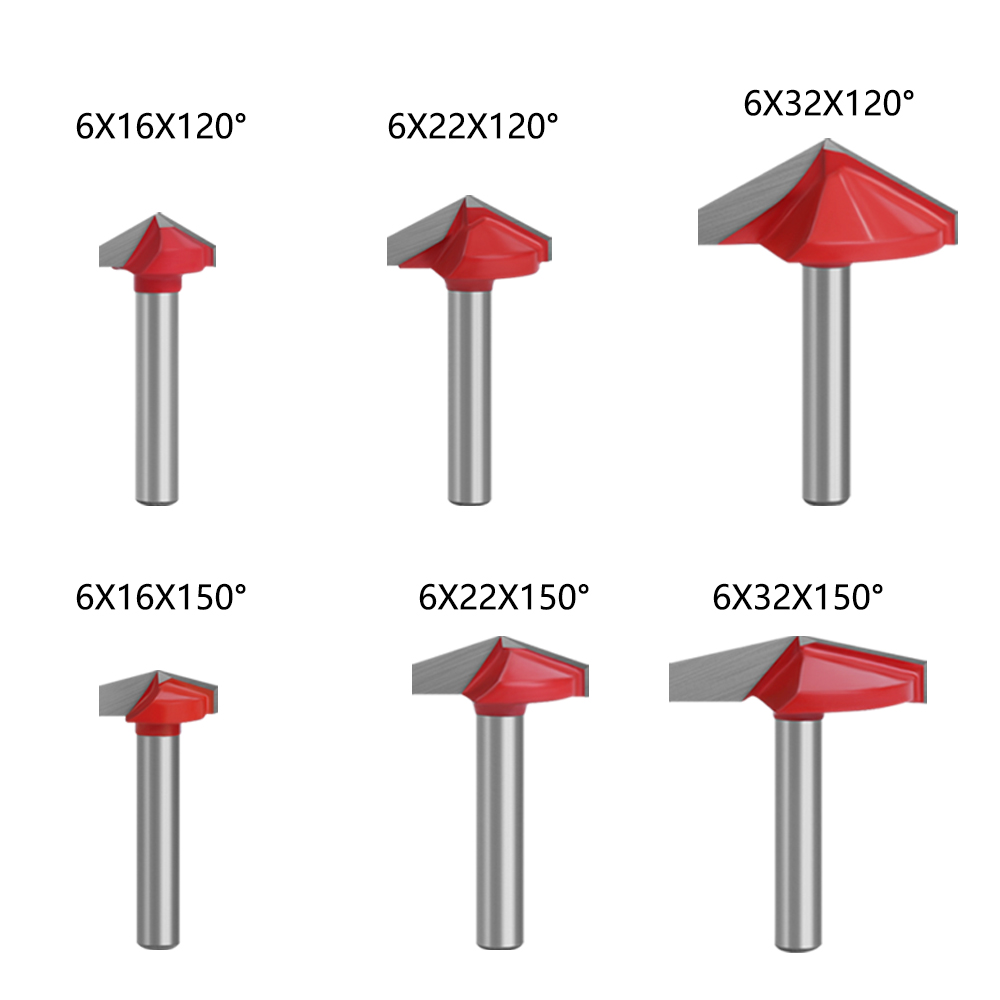
Standard straight and edge-forming bits handle general tasks, but specific manufacturing, joinery, and 3D contouring outcomes require specialized tooling geometries. Applying the wrong profile to a specialized task results in ruined parts and wasted machine time.
Designed for precise angular cuts, V-Groove Router Bits are defined by their included angle. Common specifications include 60, 90, and 120 degrees. The geometry dictates the mathematical profile depth; a steeper angle cuts deeper for a given width. A 60-degree bit will plunge significantly deeper to achieve a 1/2-inch wide groove compared to a 90-degree bit.
Primary industrial applications include chamfering edges, precise signmaking, V-carving intricate lettering, and miter-folding. In miter-folding operations, a 90-degree bit cuts through the core of a laminated sheet, leaving only the bottom veneer intact, allowing the material to be folded into a perfect seamless corner. This technique is heavily utilized in cabinet manufacturing to create seamless box columns and thick shelving.
The primary operational challenge with these cutters is low rotational velocity at the tip. At the absolute point of the V, the cutting speed is effectively zero. This lack of velocity causes the tip to scrape rather than shear, generating intense friction. Operators must adjust feed rates and utilize stepped depth passes to prevent tip-burning and material discoloration. Running a single heavy pass with a large V-groove bit will almost always scorch the bottom of the cut.
Characterized by a hemispherical cutting end, Ball Nose Router Bits are engineered for smooth contouring rather than flat-bottomed pocketing. The rounded profile eliminates sharp internal corners, reducing stress concentrations in the milled part and allowing for fluid, sweeping toolpaths.
These tools dominate 3D CNC contouring, deep fluting, fluid channel routing, and complex surface milling. When machining 3D topographies, the surface finish quality depends heavily on the step-over calculation. Step-over is the distance the tool moves laterally between parallel passes. A standard step-over percentage ranges from 8% to 12% of the tool diameter. Smaller step-overs produce a smoother surface with minimal scalloping but significantly increase machining time. Operators must balance cycle times against the manual labor required for hand-sanding the scalloped ridges.
For example, using a 1/2-inch ball nose bit with a 10% step-over means the machine moves exactly 0.05 inches laterally per pass. This tight spacing leaves microscopic ridges that can be quickly removed with 150-grit sandpaper. Pushing the step-over to 20% will cut the machine time in half but leave deep gouges that require aggressive sanding, potentially ruining the dimensional accuracy of the 3D carving.
Joinery profiles, such as rabbeting, tongue-and-groove, dovetail, and lock miter bits, require absolute alignment sensitivity. A height discrepancy of just a few thousandths of an inch can ruin the fit of a lock miter joint. Many large joinery bits incorporate anti-kickback designs. These high-mass, round-bodied bits limit the maximum chip thickness per rotation, preventing the cutter from grabbing too much material and causing dangerous kickback events.
When dealing with unidentified tooling acquired from estate auctions or long-term storage, operators must employ a strict diagnostic workflow. First, clean the bit with a resin solvent to inspect for micro-cracks in the carbide or brazing failures. Measure the shank diameter with calipers to ensure it hasn't been deformed or spun in a loose collet. Finally, test the bit at the lowest possible RPM in a router table behind a safety shield, taking incredibly light passes in scrap softwood to verify the profile and structural integrity before putting it into production service.
Incorrect bit usage introduces severe mechanical wear and operational hazards. Maintaining high standards in woodshop operations requires proactive heat management, strict adherence to speed limits, and strategic feed direction.
Thermal degradation is the enemy of both the material and the cutter. Dull edges, slow feed rates, excessive RPMs, and pitch buildup cause intense friction. This friction burns woods like cherry and maple instantly and leads to micro-cracking of the carbide edge. The formula for tool longevity involves keeping the bit clean, sharp, and moving at the correct speed.
Router Bit Diameter | Maximum Safe RPM | Typical Application |
|---|---|---|
Up to 1 inch | 24,000 RPM | Straight bits, small round-overs, flush trim |
1 inch to 2 inches | 18,000 RPM | Rabbeting bits, medium edge-forming |
2 inches to 2-1/2 inches | 16,000 RPM | Large chamfers, stile and rail bits |
Over 2-1/2 inches | 12,000 RPM | Panel raisers, large lock miters |
Operators must adhere to this strict RPM-to-diameter correlation. As the cutter diameter increases, the speed at the outer edge increases exponentially. Running a 3-inch panel raising bit at 24,000 RPM generates terrifying centrifugal forces that can bend the shank or shatter the carbide tips, turning them into lethal projectiles.
Tear-out occurs when the cutting edge lifts unsupported wood fibers. Standard routing feeds the material against the rotation of the bit. However, when dealing with highly figured grain or prone-to-splinter edges, operators may employ climb cutting. Climb cutting involves feeding the router in the same direction as the cutter's rotation. This technique presses the fibers down, virtually eliminating tear-out.
Because the bit tries to pull itself along the workpiece, climb cutting must only be performed on CNC machines or heavily secured router tables with power feeders. Attempting a heavy climb cut by hand invites severe injury as the router can violently rip out of the operator's grip. When hand-routing, operators should stick to conventional feeding and take multiple shallow passes to minimize the cutting forces that cause tear-out.
Optimizing routing operations requires aligning cutter geometry with material properties and machine capabilities. Implement the following steps to improve milling outcomes:
Standardize on 1/2-inch shank tooling for all profiles exceeding 3/8-inch cutting diameters to eliminate deflection and runout.
Match spiral geometries to the material face; use down-cut bits for delicate veneers and up-cut bits for deep pocketing where chip evacuation is critical.
Calculate and enforce strict RPM limits based on cutter diameter to prevent thermal degradation of the carbide and burning of the workpiece.
Implement stepped depth passes when utilizing zero-velocity tip profiles to manage heat generation at the point of the cut.
Clean pitch and resin from cutting flutes daily using dedicated solvents to maintain edge sharpness and prevent heat buildup.
A: Burn marks result from excessive friction. This is typically caused by feeding the material too slowly, running the router at an RPM that is too high for the bit diameter, using a dull cutting edge, or a buildup of pitch on the flutes. Increasing feed rate and lowering RPM usually resolves the issue.
A: No. It is physically impossible to fit a 1/2-inch shank into a 1/4-inch collet. While adapters exist to step down a 1/2-inch collet to accept a 1/4-inch shank, you can never size up. Attempting to modify shanks or collets compromises safety and will cause catastrophic failure.
A: A straight bit chops the material parallel to the axis of rotation, which can cause tear-out on cross-grain cuts. A spiral bit shears the material continuously at an angle, providing a much cleaner finish and actively pulling chips out of or pushing them into the cut.
A: Pitch and resin should be cleaned off as soon as visible buildup occurs. Pitch acts as an insulator, trapping heat against the carbide edge. This trapped heat destroys the temper of the metal and causes premature dulling. Use a dedicated resin solvent and a brass brush.
A: In climb cutting, the tool's rotation pulls the router in the direction of the feed. If the bit grabs the material, it can violently accelerate the router out of the operator's hands. It should only be performed taking extremely light passes or when using automated power feeders.
A: Step-over is typically set between 8% and 12% of the tool's diameter. A smaller step-over yields a smoother surface finish with smaller scallops, reducing sanding time, but increases the total machining cycle time on the CNC.


