
Views: 0 Author: Site Editor Publish Time: 2026-07-07 Origin: Site


Misaligned cope-and-stick joints and sloppy panel grooves are the fastest ways to compromise the structural integrity and aesthetic value of custom cabinet doors. Achieving perfectly flush joints requires more than just purchasing premium tooling. It demands exact micro-adjustments, perfectly milled stock, and a systematic approach to router table calibration. Without a repeatable setup process, woodworkers face wasted hardwood, weak joints, and inconsistent batch results. You cannot rely on guesswork when milling frame components. Every fraction of an inch matters when assembling a five-piece door. This guide provides an evidence-based framework for evaluating, selecting, and precisely setting up rail and stile sets to guarantee gap-free, professional-grade cabinet doors. We will cover everything from initial stock preparation to dialing in micro-shims for modern undersized plywood panels.
Bit Selection Dictates Workflow: Two-piece matched sets offer faster batch processing for high-volume work, while single reversible bits reduce upfront costs but require meticulous height recalibration between cuts.
The Three-Bit System: Complete cabinet door construction often requires a 3-bit set (rail, stile, and raised panel); understanding the setup hierarchy among all three is critical.
Stock Preparation is Non-Negotiable: Router bits reference the face and edge of the material; any deviation in stock thickness or squareness will multiply into visible joint gaps.
The Sequential Alignment Rule: Always set up and test-cut the stile (profile) first, then use that physical piece to align the height of the rail (cope) bit.
Shims Control the Tolerance: The exact fit of the tongue and groove is dictated by micro-shims (often 0.004" to 0.010" thick); understanding how to stack these is critical for accommodating variations in plywood panel thicknesses.
Test Cuts are Mandatory: Never use project stock for initial setups. Always mill extra setup blocks from the exact same batch of lumber to dial in bit height and fence alignment.
Buyers must choose a tooling configuration that balances upfront cost with long-term production efficiency. The right choice depends heavily on your shop setup and production volume. You need to evaluate how often you build doors and what kind of router table you operate.
These consist of dedicated coping (rail) and profiling (stile) cutters. Laser-etched markings on the slot cutters prevent component mix-ups. This configuration allows for two-router setups or faster bit swaps without altering the core stack height. They are ideal for production environments where speed and repeatability matter most. When you use a two-piece set, you leave the stile cutter in one router and the rail cutter in another. This eliminates the need to tear down your setup between operations. You save hours of frustration when milling large batches of cabinet doors.
These use a single arbor where cutters, bearings, and shims are physically rearranged to switch between rail and stile cuts. They offer a lower cost but are highly prone to assembly errors. You must perform complete recalibration for every profile switch. If you forget the exact shim sequence, your joints will not fit. Reversible bits work fine for hobbyists building a single vanity. They become a massive bottleneck for anyone outfitting an entire kitchen. You spend more time wrenching on the collet than actually cutting wood.
Expanding the setup to include the raised panel bit creates a complete door system. You must choose between horizontal and vertical panel-raising Woodworking Router Bits. Horizontal bits have a massive diameter. They require a powerful 3-horsepower router and multiple shallow passes. Vertical bits stand up on edge. They are safer for smaller router tables but require a tall auxiliary fence to keep the panel stable during the cut.
Different profiles demand different setup tolerances. You must match the profile to the architectural style of the cabinets.
Standard Ogee & Round-Over: Traditional profiles requiring standard bearing depths. These are forgiving and hide minor sanding mistakes.
Shaker (Square Edge): Requires bits designed for crisp 90-degree internal corners. These are highly sensitive to tear-out. You must use a fresh backer board for every cut.
45-Degree Beveled / Tapered Stiles: Specialized profiles demanding zero-tolerance height alignment. Poor alignment causes sharp, fragile edges or flat spots on the mating miter.
The cutter can only perform as accurately as the reference surfaces provided by the stock and the machine. Skipping calibration guarantees failure. You cannot fix warped wood with a router table. The machine simply follows the shape of the board.
Start by cleaning the router collet and bit shank to eliminate runout and rotational wobble. Dust buildup inside the collet causes the bit to spin off-center. This creates a wider groove than intended. Verify the router plate is perfectly flush with the table surface using a precision straight edge. If the plate sags, your cuts will be deeper in the middle of the board. Ensure the fence is exactly 90 degrees to the table to prevent tapered grooves. Use a machinist square to check the fence face.
Stock must be face-jointed, planed to a uniform thickness, and edge-jointed. The impact of even 1/64" thickness variation will multiply into severe flushness issues on the door face. You must mill all your lumber in a single session. Do not plane half your boards on Tuesday and the rest on Thursday. Changes in shop humidity will alter the thickness. Prepare dedicated setup blocks. You need a minimum of six pieces milled from the exact same project stock. Cut them to the same width as your stiles.
Milling Step | Machine Used | Tolerance Required |
|---|---|---|
Flatten Face | Jointer | Zero rock on cast iron table |
Plane to Thickness | Thickness Planer | +/- 0.005 inches across all boards |
Square One Edge | Jointer | Perfect 90 degrees to flattened face |
Rip to Width | Table Saw | Consistent width for all stiles and rails |
The stile cut establishes the groove for the center panel and the decorative inside edge. The stile is always routed first to serve as the master reference for the entire project. You will run every single vertical stile and the inside edges of every horizontal rail through this setup.
Use brass setup bars to align the center of the groove with the physical center of the stock thickness. Leave a minimum 1/8" shoulder on the back face to ensure structural integrity. If the back lip is too thin, the door will break when someone slams it shut. For standard 3/4" thick stock, aim for a 1/4" deep profile, a 1/4" groove, and a 1/4" back lip. Lock the router lift securely once you find the correct height.
Align the router table fence perfectly flush with the pilot bearing of the stile bit. Use a precision straight edge across the split-fence faces to verify alignment. The straight edge should touch the outfeed fence, the bearing, and the infeed fence simultaneously. If the fence sits behind the bearing, the bit will gouge the wood. If the fence sits proud of the bearing, the profile will be too shallow.
Run the test block face-down. Maintain firm downward pressure against the table and inward pressure against the fence. Use featherboards to keep your hands away from the cutter. Check the groove width and depth against the actual thickness of the center panel material. The panel should slide in with light friction. It should not rattle, and you should not have to force it. Once the setup is perfect, mill all your stiles and the inside edges of your rails.
The rail cut creates the negative profile that locks into the stile. Precision here dictates the strength of the final door. You will only cut the ends of the horizontal rail pieces during this step.
Disconnect power and use the previously cut stile setup block as a physical, visual gauge. Adjust the router lift height until the top and bottom cutters of the rail bit perfectly align with the back lip and sticking profile of the stile block. You want the cutting edges to slide exactly into the negative space of your test piece. Turn the collet by hand to check the alignment of both the upper and lower carbide wings.
Routing narrow rail end-grain freehand or with just a miter gauge is highly dangerous and structurally inaccurate. Secure the rail in a dedicated coping sled with a sacrificial wood backer board. This eliminates blowout and tear-out as the bit exits the cut. The backer board must be replaced when you change profiles or adjust the bit height. Clamp the rail tightly to the sled using heavy-duty toggle clamps. The wood cannot shift during the cut.
Make the test cut on a sacrificial rail block. Evaluate the physical mating. The joint should slip together under light hand pressure, remain perfectly flush on the face, and hold its own weight without adhesive. If the joint is too tight, you will starve the joint of glue. If it is too loose, the door will sag over time. Run your thumb across the face of the joint. You should not feel a step or a ridge. If you do, adjust the bit height by a few thousandths of an inch and try again.
Preparing and milling the solid wood center panel requires careful integration with the stile and rail frame. The panel must float inside the frame to allow for seasonal wood movement.
Reduce router RPM to handle large-diameter horizontal panel raisers safely. Speeds between 10,000 and 12,000 RPM are typical. Execute the cut in multiple shallow passes rather than a single heavy pass. This eliminates burning and grain tear-out. Set your fence so the bit only takes a 1/8" bite on the first pass. Move the fence back for subsequent passes until the bearing rides along the edge of the panel.
Bit Diameter | Maximum Safe RPM | Number of Passes Recommended |
|---|---|---|
Up to 1 inch | 24,000 RPM | 1 pass |
1 to 2 inches | 18,000 RPM | 1 to 2 passes |
2 to 2.5 inches | 16,000 RPM | 2 to 3 passes |
3.5 inches (Panel Raiser) | 10,000 - 12,000 RPM | 3 to 4 passes |
Adjust the bit height to match the panel tongue exactly to the groove cut by the stile bit. Utilize a panel-raiser bit with a built-in back-cutter. This ensures the front face of the raised panel sits perfectly flush with the door frame face. The back-cutter removes material from the rear of the panel simultaneously. Test the fit using your stile setup block. The panel tongue should be 1/16" shorter than the depth of the groove to allow for expansion.
Out-of-the-box Router Bits rarely match the exact thickness of modern undersized plywood panels. Nominal 1/4" plywood is often 0.220" or less. You must adjust the tooling to match the material.
Place micro-shims directly onto the bit arbor between the slot cutter and profile cutter. This adjusts the tongue and groove clearance. Most premium bit sets include a small bag of copper or steel shims ranging from 0.004" to 0.010" thick. You must loosen the arbor nut, remove the top cutter, drop the shim onto the shaft, and reassemble the stack. Ensure the cutters remain properly indexed so the carbide wings do not strike each other.
If you have a loose panel, remove shims from the stile bit stack to narrow the groove and prevent panel rattle. If you have a tight joint that will not seat, add shims to the rail bit stack to widen the tongue slot. This allows the joint to seat fully without splitting the stile. Always make adjustments in small increments. A 0.005" shim makes a massive difference in how the joint feels.
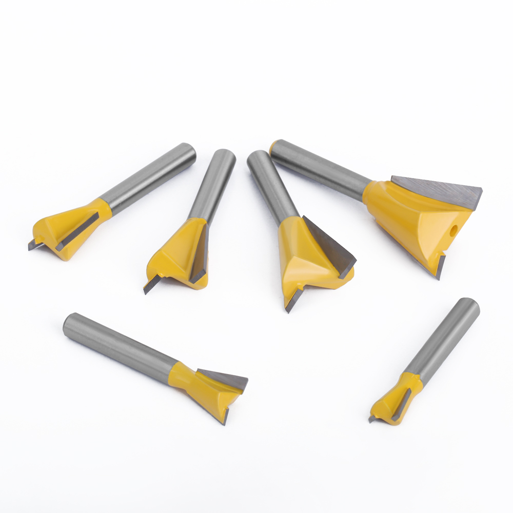
Document your shim stacks using digital calipers. Record these measurements for repeatable setups on future projects. Write the shim sequence on a piece of masking tape and stick it inside the router bit case. While drawer boxes might utilize Dovetail Joint Router Bits, cabinet doors rely entirely on these micro-adjusted cope and stick joints. Keep your shims organized in a small pillbox to prevent losing them in the sawdust.
Even with careful setup, issues can arise. Use this diagnostic table to correct common defects before you ruin expensive hardwood.
Defect | Root Cause | Corrective Action |
|---|---|---|
Misaligned Faces (Step in the Joint) | Routing with different faces against the table, or variations in stock thickness. | Always mark the show face of the lumber and keep it referenced flat on the table during every cut. |
Tapered Joints / Out-of-Square Doors | Fence is not perfectly parallel to the miter slot or bit is pulling wood away. | Utilize featherboards to maintain constant, even pressure against the fence. |
Tear-Out on Cross-Grain Cuts | Dull bits, feeding too fast, or lacking a backer board. | Implement a zero-clearance backer on the coping sled. |
Burn Marks on the Profile | Feeding too slowly or incorrect router RPM. | Adjust variable speed settings and maintain a steady feed rate. |
Joint Won't Close Completely | Sawdust trapped inside the groove or rail tongue is too long. | Blow out grooves with compressed air. Check bearing alignment on the rail bit. |
Mill all project stock and at least six setup blocks to the exact same thickness before starting your router table setup.
Calibrate your router table fence and plate to ensure perfectly square reference surfaces for the wood to ride against.
Cut the stile profile first, and use it as the physical master template for setting the rail bit height.
Build or purchase a dedicated coping sled with a sacrificial backer for all cross-grain rail cuts to prevent blowout.
Document your exact shim stacks with digital calipers to save time on future cabinet door projects.
A: Yes. Rail and stile bits require at least a 2.25 horsepower router. Large horizontal raised panel bits demand a 3 to 3.25 horsepower router to maintain safe RPMs and prevent bogging down during heavy cuts.
A: The groove cut by the stile bit is wider than your panel material. You must remove micro-shims from the stile bit arbor to narrow the slot cutter gap, matching the exact thickness of your undersized plywood.
A: It is highly discouraged. The stile creates the continuous groove that houses the panel. Cutting the stile first gives you a physical master block to accurately set the complex height of the mating rail bit.
A: Always use a coping sled equipped with a sacrificial backer board. The backer board supports the wood fibers as the bit exits the cut, completely eliminating cross-grain blowout.
A: Large diameter horizontal panel bits should be run between 10,000 and 12,000 RPM. Running them faster creates severe vibration, burns the wood, and poses a significant safety hazard.


