
Views: 0 Author: Site Editor Publish Time: 2026-09-01 Origin: Site


Selecting the wrong tooling carries hidden operational penalties that compound rapidly on the shop floor. Mismatched cutters ruin expensive stock, cause excessive machine wear, and leave poor surface finishes that demand hours of manual sanding. Critical safety hazards also increase when using low-quality cutters under heavy loads. The market floods buyers with white-labeled, budget-tier tooling, making it difficult to separate reliable equipment from disposable accessories. Operators struggle to align specific bit geometries, carbide grades, coatings, and shank sizes with their exact operational capabilities. Spindle horsepower, feed rates, and material density must dictate tool selection, not guesswork.
We introduce a technical evaluation framework to solve this problem. This guide helps buyers distinguish between standard Woodworking Router Bits and high-performance CNC Router Bits. By understanding the mechanical properties of different cutters, you can ensure the selected tooling matches the application perfectly. This approach maximizes your operational efficiency, extends the lifespan of your equipment, and minimizes costly production downtime.
Shank Diameter Dictates Stability: Defaulting to 1/2-inch shanks whenever the collet permits reduces deflection, minimizes chatter, and increases the sheer mass for heat dissipation compared to 1/4-inch shanks.
Material Composition Defines Lifespan: Solid tungsten carbide is mandatory for high-volume CNC applications and abrasive materials (MDF, plywood), while carbide-tipped bits offer a cost-effective solution for traditional edge-forming in solid wood.
Coatings Extend Tool Life: Specialty physical vapor deposition (PVD) coatings like ZrN and nACo drastically reduce thermal transfer and friction, crucial for extending the life of CNC router bits.
Flute Geometry Controls Finish: The choice between up-cut, down-cut, and compression flutes directly determines chip evacuation efficiency and which face of the material is protected from tear-out.
Application Dictates the Tool: Traditional woodworking router bits rely on bearing guides for template routing, whereas CNC router bits require plunge capabilities, precise shank tolerances, and specialized geometries for software-driven toolpaths.
Traditional routing operations prioritize smooth edge profiles and bearing-guided accuracy. Operators rely on manual feed rate control to feel the material resistance. When you push a piece of maple across a router table, you feel the resistance and hear the motor bog down, allowing you to adjust your feed rate instinctively. Success means achieving a clean profile without burning the wood. Automated routing demands different performance metrics. Machines push the tool through the material at the programmed rate regardless of resistance. Success here relies on aggressive material removal rates (MRR). Precise plunge capabilities are non-negotiable. The tooling must sustain peak performance under continuous spindle loads without premature dulling.
Operational Metric | Manual Routing | Automated Routing |
|---|---|---|
Feed Control | Tactile, reactive to material density | Programmed, constant velocity |
Tool Guidance | Bearings, fences, templates | G-code, precise coordinate systems |
Plunge Requirement | Rare, usually edge-started | Frequent, requires center-cutting geometry |
Chip Clearance | Moderate, often assisted by gravity | High-demand, requires specific flute extraction |
Manual routing introduces human variability into the cutting process. Anti-kickback designs prevent the cutter from grabbing too much material at once, limiting the chip thickness per revolution to protect the operator. Bearing guides act as physical stops for template routing, rolling along the edge of the workpiece to maintain a consistent profile depth. Manual feed rates remain inherently slower and less consistent than automated feeds. This limitation influences flute count selection. Two-flute designs typically provide the optimal finish at manual speeds. They allow sufficient time for chip clearance while maintaining a steady cut, preventing the tool from clogging with dust and overheating.
Automated operations eliminate manual guidance. Machines require center-cutting bits to plunge directly into the material, acting like a drill before moving laterally. Spindle RPM and programmed feed rates dictate the chipload. Proper chipload prevents heat buildup by transferring thermal energy into the wood chips rather than the tool body. Specific chip clearance geometries become critical at high speeds. Hand-fed safety geometries differ vastly from mechanical-feed profiles. Mechanical feeds push tools to their structural limits, demanding robust carbide and optimized shear angles to handle the aggressive material removal rates without snapping the shank.
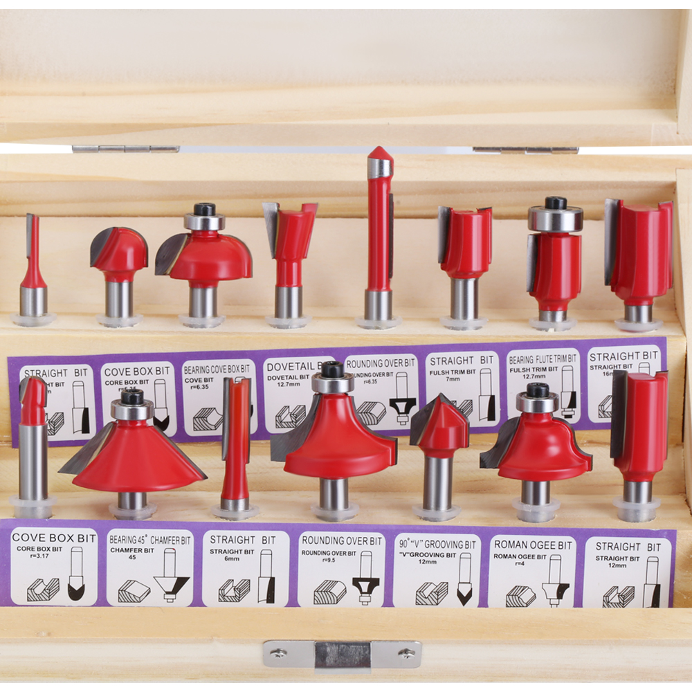
High-Speed Steel (HSS) offers a sharp initial edge. However, it dulls rapidly under friction. Use HSS strictly for low-volume softwood applications where the tool will see minimal use. Carbide-tipped tools balance durability and initial investment. They feature a steel body with brazed carbide cutting edges. This construction suits large profile cutters where solid carbide proves prohibitively expensive. Solid tungsten carbide provides superior rigidity and heat resistance. It stands as the industry standard for automated routing and abrasive composites like MDF, which contain glues that destroy softer metals instantly.
Advanced coatings further enhance tool longevity. Physical vapor deposition (PVD) coatings reduce heat build-up and friction. Zirconium Nitride (ZrN) excels when cutting non-ferrous metals like aluminum, preventing the metal from welding to the cutter. Nanocomposite (nACo) coatings protect edges against highly abrasive composites. These layers act as thermal barriers, keeping the core material stable even when the cutting edge reaches extreme temperatures during continuous production runs.
Shank diameter directly influences cut quality and tool survival. Common sizes include 1/4-inch, 8mm, and 1/2-inch shanks. Tool deflection follows strict physical laws. Doubling the shank diameter exponentially increases structural rigidity. A 1/2-inch shank deflects significantly less than a 1/4-inch shank under identical lateral loads. Reduced deflection eliminates chatter marks on the workpiece, leaving a surface that requires less sanding. It also extends the cutting edge lifespan by preventing micro-vibrations that fracture brittle carbide.
Industrial shank tolerances ensure secure collet engagement. The h6 tolerance class prevents microscopic slipping in high-speed spindles. To ensure maximum rigidity and minimize runout, operators should follow a strict collet loading procedure:
Clean the inside of the spindle taper with a specialized wiper to remove dust and resin.
Snap the collet into the collet nut before inserting the tool or threading it onto the spindle.
Insert the tool shank, leaving a 1/8-inch gap at the bottom of the collet to prevent binding and allow proper compression.
Tighten the nut to the manufacturer's specified torque using a proper wrench, avoiding over-tightening which distorts the collet.
Flute geometry determines how the tool interacts with the material fibers. Different spirals yield vastly different outcomes depending on the material and the desired finish.
Flute Type | Chip Evacuation | Primary Application | Tear-Out Risk |
|---|---|---|---|
Straight Flute | Neutral (lateral) | General grooving, basic edge work | Moderate on both faces |
Up-cut Spiral | Pulls chips upward | Deep mortises, high-volume clearing | High on top surface |
Down-cut Spiral | Pushes chips downward | Shallow dados, veneered surfaces | High on bottom surface |
Compression Spiral | Pulls toward the center | Double-sided laminates, plywood | Zero on both faces |
Straight flutes chop material rather than shearing it. They hit the wood fiber parallel to the grain, acting like an axe. Up-cut spirals excel at deep mortises but splinter the top surface as they lift the fibers. Down-cut spirals leave a pristine top surface but require slower feed rates due to restricted chip clearance, as they pack the dust into the bottom of the cut. Compression spirals combine both geometries. They pull the top and bottom surfaces inward. This makes them the ultimate solution for tear-out-free cuts in double-sided melamine and veneered plywood.
Edge forming tools shape the perimeter of a workpiece. Roundovers, chamfers, ogees, and cove bits dominate this category. The shear angle of the brazed carbide dictates the finish quality. A higher shear angle slices wood fibers cleanly, acting like a slicing knife rather than a blunt wedge. This reduces sanding time on end-grain surfaces, which are notoriously difficult to finish. Proper bearing alignment ensures the profile remains consistent across the entire edge, preventing the cutter from digging too deeply into the stock.
Mechanical joints require exact dimensional accuracy. Straight, spiral, dovetail, and rabbeting bits facilitate these connections. Precise diameter tolerances ensure tight-fitting joints. A groove cut with an undersized bit ruins the assembly process. For example, standard 3/4-inch plywood is rarely exactly 3/4-inch thick; it is usually closer to 23/32-inch. Operators must use specific undersized Router Bits to cut dados that actually fit modern sheet goods tightly without slop.
Automated platforms utilize specialized geometries designed for specific toolpaths. Spoilboard surfacing cutters flatten large bed areas efficiently, ensuring the workpiece sits perfectly parallel to the gantry. Insert-carbide surfacing tools allow operators to rotate dull knives to a fresh edge instead of replacing the entire tool body. V-groove and engraving tools feature specific included angles. Angles of 60 or 90 degrees produce crisp lettering for sign-making and chamfered edges on complex parts. Ball nose cutters handle 3D carving. Operators must calculate exact step-over requirements to achieve smooth topographical modeling without leaving prominent ridges between passes.
Budget cutters carry hidden operational penalties that manifest during production. Poor balancing causes premature spindle bearing wear, leading to expensive machine repairs. Thin carbide layers prevent professional resharpening, forcing you to throw the tool away after its first lifecycle. Brittle brazing creates severe safety hazards if the carbide detaches at 20,000 RPM. Premium cutters utilize micro-grain carbide for sharper, longer-lasting edges. The smaller the grain structure, the sharper the edge it can hold without crumbling. They feature PTFE coatings to resist pitch build-up, keeping the tool cool. Computer-balanced shanks ensure vibration-free rotation at maximum spindle speeds.
High-production environments benefit from insert-tooling. Replaceable carbide knives offer immediate edge renewal without altering tool length offsets in the machine controller. Disposable brazed cutters suit lower-volume shops where tool changes are infrequent. Professional sharpening services extend the life of solid carbide spirals. You can send these tools out for regrinding, which removes a few thousandths of an inch from the diameter. Operators must update their tool library software with the new exact diameter, or the machine will cut parts slightly oversized.
Friction burns wood and overheats carbide. Overheating leads to rapid edge failure, turning a sharp tool into a blunt instrument in minutes. Calculating and maintaining the correct chipload mitigates this risk. Balance the spindle RPM with the linear feed rate. A fast spindle and slow feed rate cause rubbing, generating smoke and destroying the temper of the cutter. A slow spindle and fast feed rate cause tool breakage, snapping the shank under excessive lateral load. Proper chipload ensures the heat leaves the cut via the wood chips, keeping the tool body cool to the touch.
Feed direction influences surface finish and workholding stability. Conventional milling pushes the tool against the feed direction. It provides safer manual operation because the rotation pushes the workpiece back toward the operator, allowing for controlled resistance. Climb milling pulls the tool along the cut path. It yields superior surface finishes because the cutting edge shears the material at maximum thickness and exits at zero thickness. Automated machines utilize climb milling extensively for finish passes. Manual operators must avoid climb cutting on router tables to prevent the tool from grabbing and violently throwing the workpiece.
Microscopic wobbling causes tool breakage and poor cut quality. This wobble is called runout. Proper seating prevents runout. Leave a 1/8-inch gap at the bottom of the collet to avoid bottoming out, which prevents the collet from compressing evenly around the shank. Clean collets regularly with brass brushes and specialized solvents to remove baked-on resin and dust. Replace worn collets every 400 to 600 hours of use. A degraded collet loses its elasticity and cannot grip the shank securely, leading to catastrophic tool slip during heavy cuts.
Audit your current collet conditions and replace any hardware showing visible wear, scoring, or rust to ensure secure shank engagement.
Map your primary machine capabilities and material types to select the exact flute geometries needed, avoiding generic multi-piece kits that contain unused profiles.
Invest in a targeted set of solid carbide compression spirals if processing double-sided laminates or veneered plywood on automated equipment.
Calculate your optimal chipload before running new materials to prevent friction burning, optimize feed rates, and extend carbide lifespan.
A: An up-cut spiral pulls wood chips upward, clearing deep cuts efficiently but causing splintering on the top surface. A down-cut spiral pushes chips downward, leaving a perfectly clean top edge but requiring slower feed rates to prevent chip packing in the groove.
A: While shank sizes may fit, traditional cutters are generally unsuitable for automated toolpaths. They often lack center-cutting plunge capabilities. Bits with bearing guides pose severe crash risks if programmed incorrectly.
A: Burning occurs when the spindle RPM is too high relative to the feed rate. The bit rubs against the wood rather than shearing it, generating extreme friction. Pitch buildup on the cutting edge also accelerates heat transfer and burning.
A: A 1/2-inch shank provides exponentially more rigidity, reducing deflection and vibration. However, 1/4-inch shanks remain necessary for compact trim routers or highly detailed, small-diameter work where a large shank cannot physically fit.
A: Compression cutters combine up-cut and down-cut geometries. They pull both the top and bottom surfaces of the material inward toward the center. This design prevents tear-out on both faces of laminated materials and plywood.
A: Solid carbide typically retains its sharp cutting edge 10 to 25 times longer than HSS. This durability is especially critical when processing abrasive manufactured materials like MDF or fiberglass.


